This page documents the engine design and development work carried out by EBD for Godden Racing, a specialist manufacturer of single cylinder engines for grasstrack and speedway competition. The brief was straightforward in its goals and demanding in execution: improve power output, reduce overall weight, and deliver a design manufacturable either as a machined-from-solid prototype or as a production magnesium alloy casting.
The result was an engine producing approximately 63 BHP from a package weighing under 30 kilograms. In automotive terms, that is the equivalent of a normally aspirated 2.0 litre engine producing 250 BHP straight from the build. The work spanned full component CAD design, thermal analysis, structural FEA, and a complementary rocker optimisation study on the PPP-106 that applied and refined the same analytical methods.
The Engineering Challenge
Speedway engines are among the most extreme powerplants in motorsport, and extreme in ways that are not immediately obvious from the outside. There is no gearbox. The engine fires, the clutch drops, and from that point the drivetrain is a direct mechanical path from crankshaft to rear wheel. Every newton-metre of torque has to arrive at the right time from a standing start, with no gear ratio selection available to manage the power delivery. This places exceptional demands on torque curve shape at low and mid RPM - not just at peak power - because the engine must pull hard from the moment it is asked to.
The fuel is methanol. Methanol has a significantly higher latent heat of vaporisation than petrol, producing a charge cooling effect that improves volumetric efficiency and allows higher compression ratios. In return it demands larger fuel delivery sizing and behaves differently through combustion - ignition timing, compression ratio, port design and combustion chamber shape all interact differently on methanol than on petrol. An engine designed around methanol from the outset will always outperform one adapted to it after the fact.
Without a gearbox, the engine has nowhere to hide mechanically. Every reciprocating component carries the full inertia load every cycle, at operating RPM, with nothing in the drivetrain to absorb transients. Inertia force on the piston scales with the square of RPM - double the speed and the peak force quadruples. This is why reducing reciprocating mass is not just about improving throttle response. It directly reduces peak loads on bearings, the piston pin, and every structural element in the bottom end. Less mass at a given RPM means lower peak force, which means either a lighter component achieving the same fatigue life, or the same component achieving a longer one. That trade-off sits at the centre of every decision in a competitive speedway engine build.
Magnesium Alloy – Design Rationale
The production intent for the Godden engine casings was magnesium alloy casting. Magnesium is approximately 35% lighter than aluminium at equivalent structural sections - a significant margin on an engine where casing mass contributes nothing to power output. For a component that is entirely parasitic weight, the case for using the lightest material that meets structural and thermal requirements is straightforward.
However, designing for magnesium casting is not simply a matter of scaling down an aluminium design. Magnesium has a lower elastic modulus than aluminium, a different thermal expansion coefficient, and minimum wall thickness requirements that differ from aluminium to avoid shrinkage porosity in the cast sections. Stiffness must come from geometry - ribs, bosses, and section profiles - rather than from bulk material. This is a fundamentally different design philosophy to machining from solid, where sections can be thickened locally without penalty during the prototype phase.
The initial prototype route was machined from solid billet specifically to allow the design to be validated dimensionally and functionally before committing to casting tooling. Critically, the CAD model was designed to the casting geometry from the outset - draft angles, fillet radii, and consistent wall sections were incorporated at the first revision. This avoids the common and expensive failure mode of producing a machined prototype that cannot be directly cast without a partial redesign.
Component Design – CAD
Engine Assembly
The complete engine assembly was developed as a full 3D parametric CAD model, enabling clearance checking, mass properties extraction, and centre of gravity calculation for vehicle installation. The renders below show the finished design at the point of handover for prototype manufacture. Click any image to expand and zoom.


Pump Housing
The pump housing was one of the primary structural castings designed during the project. External envelope was minimised while maintaining adequate port cross-sections for flow, with bosses for sealing interfaces and fastener positions sized and located for assembly access. Wall thickness was held consistent throughout to support the magnesium casting route and avoid localised shrinkage defects.


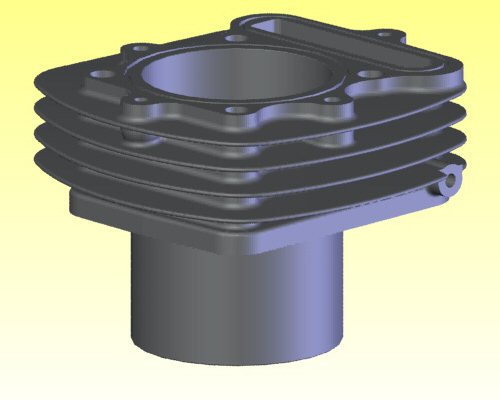
Engine Barrel – Thermal and Stress FEA
The engine barrel received the most detailed analytical treatment on this project. In a high-output single cylinder engine, the barrel bore is subjected simultaneously to a thermal gradient through the wall and a mechanical pressure load on every firing stroke. Structural integrity of the barrel itself is not the primary concern at these power levels with a well-designed casting. The concern is bore distortion under operating conditions.
What FEA Tells You About Bore Distortion
Bore distortion is not visible during assembly and does not announce itself cleanly during operation. It manifests as increased blow-by past the ring pack, elevated oil consumption, and accelerated ring and bore wear. These effects degrade performance progressively and are difficult to attribute to bore distortion specifically without pressure trace data, because the symptoms are identical to ring bedding issues or marginal ring tension.
Thermal FEA predicts the steady-state temperature distribution through the barrel wall under representative operating conditions. The temperature gradient from the combustion face to the fin tips creates differential thermal expansion - the hot inner wall wants to grow more than the cooler outer sections, and the resulting strain distorts the bore away from its machined circular form. Structural FEA then adds the mechanical loading from peak cylinder pressure, which acts on the bore wall as a hoop stress and compounds the thermal distortion.
The two effects are not simply additive, because the thermal pre-strain changes the stiffness of the structure in the loaded condition. Combining both loads in a single coupled analysis gives the actual bore profile at the worst-case operating point - typically close to peak power at high coolant temperature - which is the condition that determines whether ring seal is maintained throughout the engine's operating envelope. The analysis confirmed that the barrel design maintained bore distortion within acceptable limits, validating the wall thickness and fin geometry selected for the production casting.

Case Study: PPP-106 Rocker FEA
Alongside the Godden engine programme, the same FEA methodology was applied to the valve train rockers on the PPP-106 sprint engine. The study is documented here because it shares the same analytical approach and illustrates the same principle: model the actual component under real loading before making any changes, and let the data determine what to do.
The Conventional Wisdom – and Why It Is Wrong
The widely accepted modification in the 106 Rallye tuning community is to replace the standard aluminium rockers with cast iron items. The reasoning is that cast iron is stronger, so it will handle the higher valve spring loads and RPM of a tuned engine better than the original aluminium castings. On the surface this sounds plausible. The problem is that cast iron is approximately three times denser than aluminium. A cast iron rocker geometrically similar to the aluminium original will be roughly three times heavier. In a reciprocating valve train, that extra mass is not neutral - it is actively harmful.
Inertia force on a rocker scales as F = m·a. At a given RPM, the acceleration is fixed by the cam profile, so force is directly proportional to mass. A rocker three times heavier generates three times the inertia force on the cam lobe, the rocker shaft, and the valve stem at the same RPM. The very modification intended to strengthen the valve train substantially increases the load on every component in it. At 8,500 rpm with a stiff valve spring, the inertia term dominates, and increasing rocker mass is the wrong direction.
The Analysis
The FEA study started from the standard aluminium rocker with no predetermined outcome. Loading was applied based on the measured spring characteristics of the CATCAMS PAC-S10011 single valve springs fitted to the PPP-106, at the design RPM of 8,500 rpm.
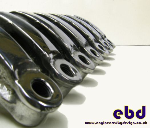
The finished modified rockers. Material removed from low-stress regions identified by FEA, section transitions blended to remove stress raisers. The polished surface finish is not cosmetic - surface condition directly affects fatigue life on a cyclically loaded component. Click to expand.
The displacement plot from the baseline model identified two things. First, a significant proportion of the rocker cross-section was carrying very low stress - material contributing mass without contributing meaningfully to structural performance. Second, the original casting had geometric stress concentrations at section transitions - sharp internal radii and abrupt changes in cross-section that locally amplified peak stress well above the nominal section value.
Two Separate Effects – One Combined Result
The geometry modification addressed both findings independently, and it is important to understand them as separate contributions to the overall improvement:
Mass reduction. Material was removed from the low-stress regions identified by the FEA, reducing rocker mass by over 5 grams per rocker. For a component of approximately 40-45 grams, this is around 11% mass reduction. By F = m·a, this reduces peak inertia loading on the valve train by 11% at any given RPM. From the relationship RPMnew = RPMold × √(mold / mnew), an 11% mass reduction gives approximately 6% additional RPM headroom from inertia loading alone.
Stress concentration removal. The section transitions were re-profiled with generous blend radii, removing the geometric stress raisers identified in the baseline model. Stress concentrations are multiplicative - a concentration factor (Kt) of even 1.5 means the peak local stress is 50% above the nominal section stress. Removing these raises the effective fatigue strength of the component independently of the mass saving. This is the second, separate contribution to the overall result.
The combined result of both changes was a 12.5% improvement in reliable operating capability at the design RPM. This figure reflects the net improvement to the rocker's stress margin - it is not solely a mass-derived RPM number, and presenting it as such would overstate the contribution of weight saving alone. Both effects matter, and both were the direct result of the FEA identifying where the real problems were in the original design.
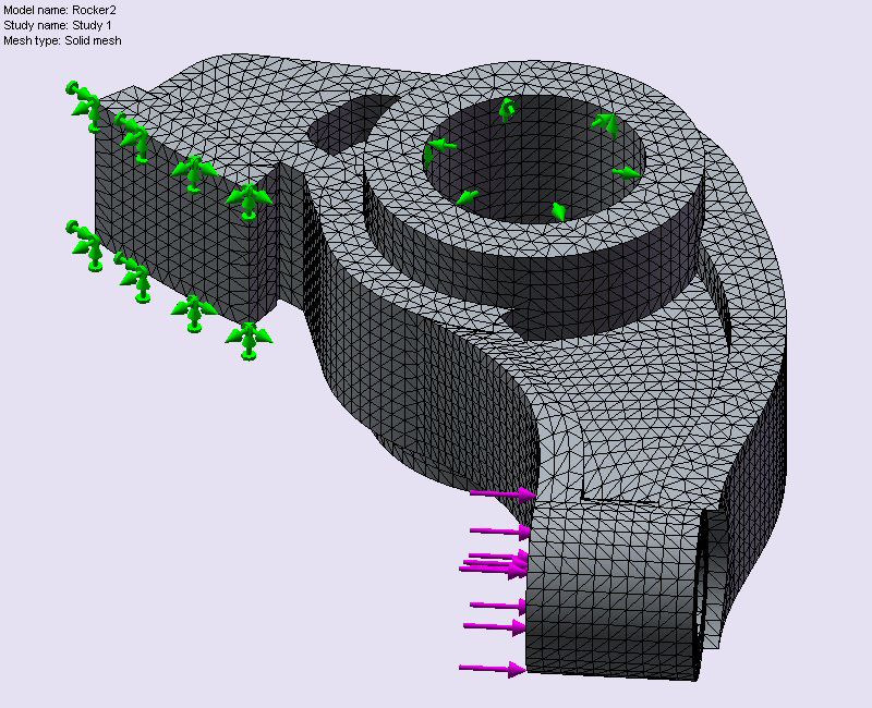
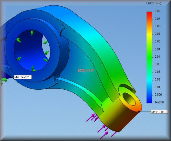
Left: solid mesh with boundary conditions - green arrows show the fixed constraint at the rocker shaft bore, pink arrows show the valve spring load at the pad end. Right: URES resultant displacement plot - maximum deflection 0.06 mm at the valve end under full spring load at 8,500 rpm. The colour gradient from blue to orange-red identifies where the rocker is working hardest and where material can safely be removed. Click either image to expand and zoom.
Deflection Animation
The animation below shows the deflection cycle on the standard rocker geometry under dynamic loading. The displacement scale is exaggerated to make the deformation mode visible - in service the actual deflection is sub-tenth of a millimetre, but the shape of the deformation identifies exactly where the geometry needs attention.
Displacement scale is exaggerated for visibility. In service, actual deflection is sub-tenth of a millimetre.