A reference guide to piston component identification. Understanding piston anatomy is essential for engine specification, ring selection, con-rod fitment, and failure analysis. The diagram below covers the main body features and the ring groove detail that determines ring selection and sealing performance.
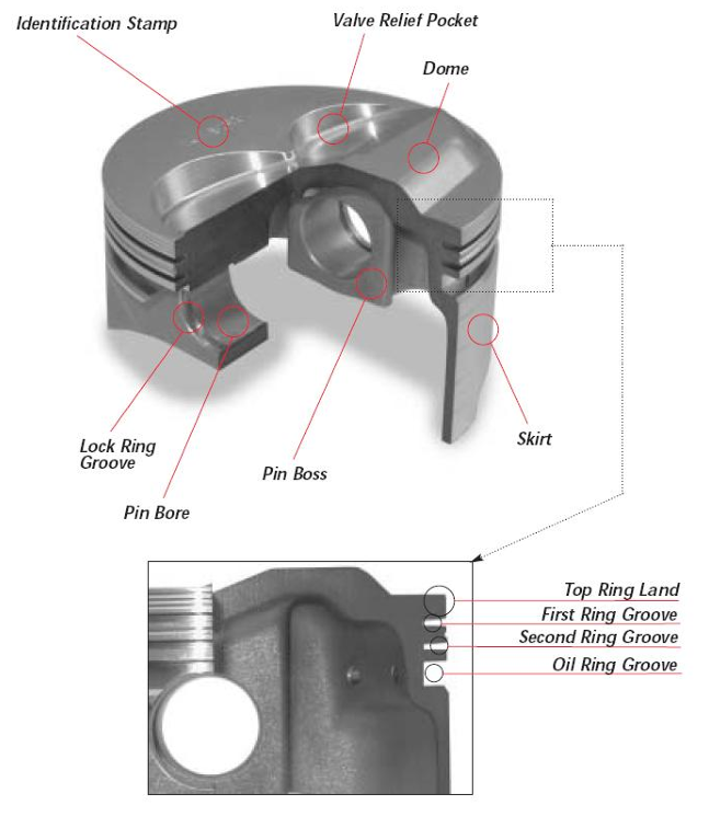
Piston cross-section showing main components (upper) and ring groove detail (lower). Red callout circles indicate each labelled feature.
Component Reference
| Component | Function | Engineering Notes |
|---|---|---|
| Crown / Dome | Top surface of the piston that forms part of the combustion chamber | Flat, dished, or domed depending on target compression ratio and combustion chamber shape. Dome volume is subtracted when calculating effective compression ratio |
| Valve Relief Pocket | Recessed areas machined into the crown to provide valve clearance at TDC | Critical dimension - insufficient clearance causes piston-to-valve contact. Depth and position must match cam timing, valve lift and con-rod length. Minimum clearance typically 1.5-2.0 mm on a road engine, 1.0 mm on a race engine with careful measurement |
| Identification Stamp | Manufacturer part number, bore size, and orientation marking | Arrow or notch typically indicates installation orientation relative to engine front. Always verify before assembly - incorrect orientation can misalign valve reliefs |
| Top Ring Land | Land area between the crown and the first ring groove | Height determines combustion gas exposure area above the top ring. Taller land reduces heat transfer to rings but increases crevice volume and unburnt hydrocarbons |
| First Ring Groove | Houses the top compression ring - primary combustion seal | Takes the highest thermal and mechanical load. Ring side clearance is critical - too tight risks seizure, too loose causes excessive blowby and ring flutter at high rpm. Typically 0.04-0.07 mm side clearance |
| Second Ring Groove | Houses the second compression ring - backs up the primary seal and assists oil control | Acts as a scraper to return oil that passes the oil ring. Ring face taper or step orientation affects scraping action direction - install correctly per manufacturer marking |
| Oil Ring Groove | Houses the three-piece or one-piece oil control ring | Wider groove than compression rings. Radial drain holes in the groove floor return scraped oil to the sump via piston internals. Blocked drain holes are a common cause of oil consumption |
| Piston Skirt | Lower cylindrical section that bears side thrust loads against the bore | Skirt profile (barrel, taper or cam-ground oval), clearance and coating directly affect noise, friction and wear rate. Slipper skirts reduce reciprocating mass and friction. Clearance typically 0.02-0.06 mm depending on alloy and application |
| Pin Boss | Reinforced internal boss that supports the gudgeon pin | Heavily loaded component - transfers all combustion and inertia loads between piston and con-rod via the pin. Boss height determines pin centre height relative to the crown, which affects compression ratio and con-rod angle geometry |
| Pin Bore | Precision bore through the pin boss that the gudgeon pin passes through | Bore-to-pin clearance varies by arrangement. Full floating pins (free to rotate in both piston and rod) require 0.005-0.015 mm clearance. Press-fit pins (fixed in rod) use interference fit in the rod small end, clearance in piston bore |
| Lock Ring Groove | Circumferential groove at each end of the pin bore that retains the circlip | Used with full-floating pin arrangements only. Circlip (snap ring) prevents axial migration of the pin into the bore wall. Always use new circlips on rebuild - never reuse. Ensure circlip is fully seated in groove before assembly |
Related Pages
Piston Kinematics & Dynamics
PPP-106 engineering study. Piston acceleration, peak force, con-rod stress and factor of safety. Includes interactive calculator.
BSFC & Injector Sizing
Brake Specific Fuel Consumption, thermal efficiency and injector flow rate calculator.
Bolt Torque Reference
Recommended torque values by bolt grade, size and thread pitch for engine assembly fasteners.